)
TripleO (OpenStack On OpenStack) is a program aimed at installing, upgrading and operating OpenStack clouds using OpenStack’s own cloud facilities as the foundations – building on Nova, Neutron and Heat to automate fleet management at datacenter scale.
If you read the TripleO setup for network isolation, it lists eight distinct networks. Why does TripleO need so many networks? Let’s take it from the ground up.
Table of contents
- WiFi to the workstation
- Provisioning network
- Deploying the overcloud
- Deploying and using a virtual machine
- Tenant networks
- Wrap Up
WiFi to the workstation

I run Red Hat OpenStack Platform (OSP) Director, which is the productized version of TripleO. Everything I say here should apply equally well to the upstream and downstream variants.
My setup has OSP Director running in a virtual machine (VM). To get that virtual machine set up requires network connectivity. I perform this via wireless, as I move around the house with my laptop. The workstation has a built-in wireless card.
Let’s start here: Director runs inside a virtual machine on the workstation. It has complete access to the network interface card (NIC) via macvtap. This NIC is attached to a Cisco Catalyst switch. A wired cable to my laptop is also attached to the switch. This allows me to set up and test the first stage of network connectivity: SSH access to the virtual machine running in the workstation.
Provisioning network
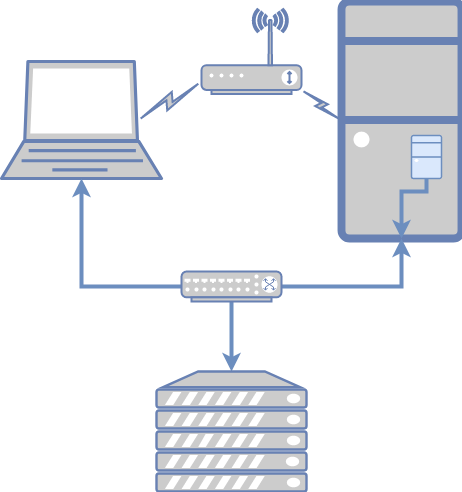 The blue network here is the provisioning network. This reflects two of the networks from the TripleO document:
- IPMI* (IPMI System controller, iLO, DRAC)
- Provisioning* (Undercloud control plane for deployment and management)
These two distinct roles can be served by the same network in my set up, and, in fact they must be. Why? Because my Dell servers have a NIC that acts as both the IPMI endpoint and is the only NIC that supports PXE. Thus, unless I wanted to do some serious VLAN wizardry, and get the NIC to switch both (tough to debug during the setup stage), I’m better off with them both using untagged VLAN traffic. This way, each server is allocated two static IPv4 address, one used for IPMI and one that will be assigned during the hardware provisioning.
Apologies for the acronym soup. It bothers me, too.
Another way to think about the set of networks that you need is via DHCP traffic. Since the IPMI cards are statically assigned their IP addresses, they don’t need a DHCP server. But the hardware’s operating system will get its IP address from DHCP. So it’s OK if these two functions share a network.
This doesn’t scale very well. IPMI and IDrac can both support DHCP and that would be the better way to go in the future, but it’s beyond the scope of what I’m willing to mess with in my lab.
Deploying the overcloud
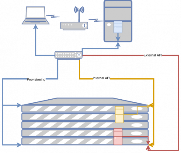 In order to deploy the overcloud, the director machine needs to perform two classes of network calls:
- SSH calls to the bare metal OS to launch the services, almost all of which are containers. This is on the blue network above.
- HTTPS calls to the services running in those containers. These services also need to be able to talk to each other. This is on the yellow internal API network above. (I didn’t color code “yellow” as you can’t read it. )
Internal (not) versus external
You might notice that my diagram has an additional network; the external API network is shown in red.
Provisioning and calling services are two very different use cases. The most common API call in OpenStack is POST https://identity/v3/auth/token. This call is made prior to any other call. The second most common is the call to validate a token. The create token call needs to be access able from everywhere that OpenStack is used. The validate token call does not. But, if the API server only listens on the same network that’s used for provisioning, that means the network is wide open; people who should only be able to access the OpenStack APIs have the capability to send network attacks against the IPMI cards.
To split this traffic, either the network APIs need to listen on both networks or the provisioning needs to happen on the external API network. Either way, both networks are going to be set up when the overcloud is deployed.
Thus, the red server represents the API servers that are running on the controller and the yellow server represents the internal agents that are running on the compute node.
Some Keystone history
When a user performs an action in the OpenStack system, they make an API call. This request is processed by the web server running on the appropriate controller host. There’s no difference between a Nova server requesting a token and project member requesting a token. These were seen as separate use cases and were put on separate network ports. The internal traffic was on port 35357 and the project member traffic was on port 5000.
It turns out that running on two different ports of the same IP address doesn’t solve the problem people were trying to fix. They wanted to limit API access via network, not by port. Therefore, there really was no need for two different ports, but rather two different IP addresses.
This distinction still shows up in the Keystone service catalog, where endpoints are classified as external or internal.
Deploying and using a virtual machine
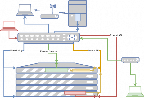
Now our diagram has become a little more complicated. Let’s start with the newly added red laptop, attached to the external API network. This system is used by our project member and is used to create the new virtual machine via the compute create_server API call.
Here’s the order of how it works:
- The API call comes from the outside, travels over the red external API network to the Nova server (shown in red)
- The Nova posts messages to the the queue, which are eventually picked up and processed by the compute agent (shown in yellow).
- The compute agent talks back to the other API servers (also shown in red) to fetch images, create network ports and connect to storage volumes.
- The new VM (shown in green) is created and connects via an internal, non-routable IP address to the metadata server to fetch configuration data.
- The new VM is connected to the provider network (also shown in green.)
At this point, the VM is up and running. If an end user wants to connect to it they can do so. Obviously, the provider network doesn’t run all the way through the router to the end user’s system, but this path is the open-for-business network pathway.
Note that this is an instance of a provider network as Assaf Muller defined in his post.
Tenant networks
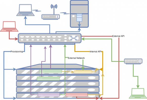
Let’s say you’re not using a provider network. How does that change the set up? First, let’s re-label the green network as the external network. Notice that the virtual machines don’t connect to it now. Instead, they connect via the new purple networks.
Note that the purple networks connect to the external network in the network controller node, show in purple on the bottom server. This service plays the role of a router, converting the internal traffic on the tenant network to the external traffic. This is where the floating IPs terminate and are mapped to an address on the internal network.
Wrap up
The TripleO network story has evolved to support a robust configuration that splits traffic into component segments. The diagrams above attempt to pass along my understanding of how they work and why.
I’ve left off some of the story, as I don’t show the separate networks that can be used for storage. I’ve collapsed the controllers and agents into a simple block to avoid confusing detail: my goal is accuracy, but here it sacrifices precision. It also only shows a simple rack configuration, much like the one here in my office. The concepts presented should allow you to understand how it would scale up to a larger deployment. I expect to talk about that in the future as well.
I’ll be sure to update this article with feedback. Please let me know what I got wrong and what I can state more clearly.
About the author
Adam Young is a cloud solutions architect at Red Hat, responsible for helping people develop their cloud strategies. He has been a long time core developer on Keystone, the authentication and authorization service for OpenStack. He’s also worked on various systems management tools, including the identity management component of Red Hat Enterprise Linux based on the FreeIPA technology. A 20-year industry veteran, Young has contributed to multiple projects, products and solutions from Java based eCommerce web sites to Kernel modifications for Beowulf clustering. This post first appeared on his blog.
Cover photo // CC BY NC
- TripleO networks: From simplest to not-so-simple - January 14, 2019
- How to create a self trust In Keystone - October 29, 2018
- Using JSON home on a Keystone server - February 5, 2018